Thursday, December 26, 2013

Slight diversion

Only had single day off over holidays to work on car, so decided to take a slight diversion away from the chassis focus and devoted some time to the interior. Given the limited amount of interior space inside a Mini, picked up a Kirkey aluminum race seat (will be adding a second for passenger side) that should work quite nicely given the narrow seat width.

The seats are quite comfortable to sit in, but would prefer to have some creature comforts for longer street drives, so the plan is to add some additional foam inserts for the lower and upper seat backs and then have them upholstered in some distressed black leather that I picked up.

Decided the seat foam will need to have some additional strength, so got started on fabricating some fiberglass pans for lower and upper seat portions.

Applied some simple aluminum foil to the seat to protect seat and aid in releasing resin, cut the fiberglass mat material (few layers), and got started with applying the resin. When the resin hardened, cut the fiberglass to the required size using an air powered hacksaw. More to follow.


Thursday, December 5, 2013

Chassis tubing begins...

Picked up quite a number of lengths of 1.5"x1.5"x.120" square tubing. Our plan is to build out the lower chassis rails and cross-members with the intention of allowing the front and rear S2000 factory sub-frames to bolt into the new chassis.  This strategy will allow both the engine and transmission, and rear suspension assemblies to drop from the bottom while the car is on the lift should full service of either ever be required.

Starting from the rear and working forward, we began by mocking up short lengths of tubing to get an idea of where the factory sub-frame mounting location points would need to be transferred to the tubing.


Fired up the mill and drilled some 1" holes into the tubing into which some 5/8" NF threaded steel bungs were installed and then welded into place. The rear rails also required some short steel spacer blocks to be welded in place in order to permit the rails to clear the rear upper control arm mounts.


Next up was to calculate the necessary angles in the tubing rails required to meet up with the front mounting hole location on the rear sub-frame. Once that was figured out, cut the tubing and welded the sections together.


Used the same approach to start work on the main rear cross-member which also required jog at the mounting pads in order to maintain the desired floor pan depth.


Using some heavier gauge metal, bent up some new inner rocker panels and welded them in to the outer factory rocker panels with a series of plug welds. This new panel will be used to mount the chassis floor structure to the body.


Friday, August 23, 2013

Body and engine mock up


Now that the front and rear S2000 subframes have been set at the factory default ride heights and desired wheelbase, and temporarily tack welded to the chassis table, we can begin further mock up.

Since we didn't acquire a set of factory rubber engine mounts with the engine assembly we picked up, and the price of new mounts was on par with aftermarket mounts, aftermarket mounts were selected.


Time to temporarily mount the engine and transmission in place using the new engine mounts, and adding a brace to the table to support the transmission at correct pinion angle for driveshaft alignment. It's obvious at this point that a new shorter driveshaft will be in order.


Dropping the body on now will allow us to figure out a few things:

  1. How low we can go with the body over the chassis, with the limiting factor being the top of the engine.
  2. How far the engine and transmission will protrude into the drivers compartment.


First order of business is to cut the remaining cowl panel from the Mini shell.


We then used the shop car lift to raise the body shell up, rolled the table back under, and then lowered the shell back down over the table to position the shell which took a few attempts in order to obtain the desired height.


Just for kicks, dropped the nose back over the front to get some perspective... looks like there's still some margin for further lowering.


Next on the agenda is to get busy laying down some actual tubing....stay tuned....

Tuesday, June 25, 2013

Chassis work begins.....

Completed as much of the body panel replacement as possible to this point, so focus now shifts to getting the chassis started.

First step is getting the front and rear S2000 subframes up on to the chassis table,


and then locating them at the correct factory ride heights, as well as establishing the new wheel base at 84", an increase of close to 4" which we will make up in the front end.

Picked up a set of front S2000 frame rails from a guy that was parting a damaged car. Fired up the plasma cutter and cut out only the relevant sections that will be required. Plan is to only use these factory rails as reference in the creation of a fixture that will be used to locate the upper control arm and strut location points. These points will be transferred to the new tube chassis when we get to that stage.


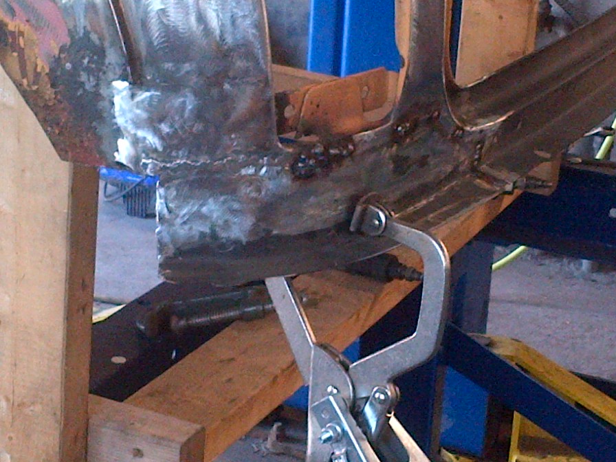
Once everything is established, measured and cut up some short sections of tubing and used these to tack weld the subframes to the table to ensure we maintain the correct location points during chassis build up.


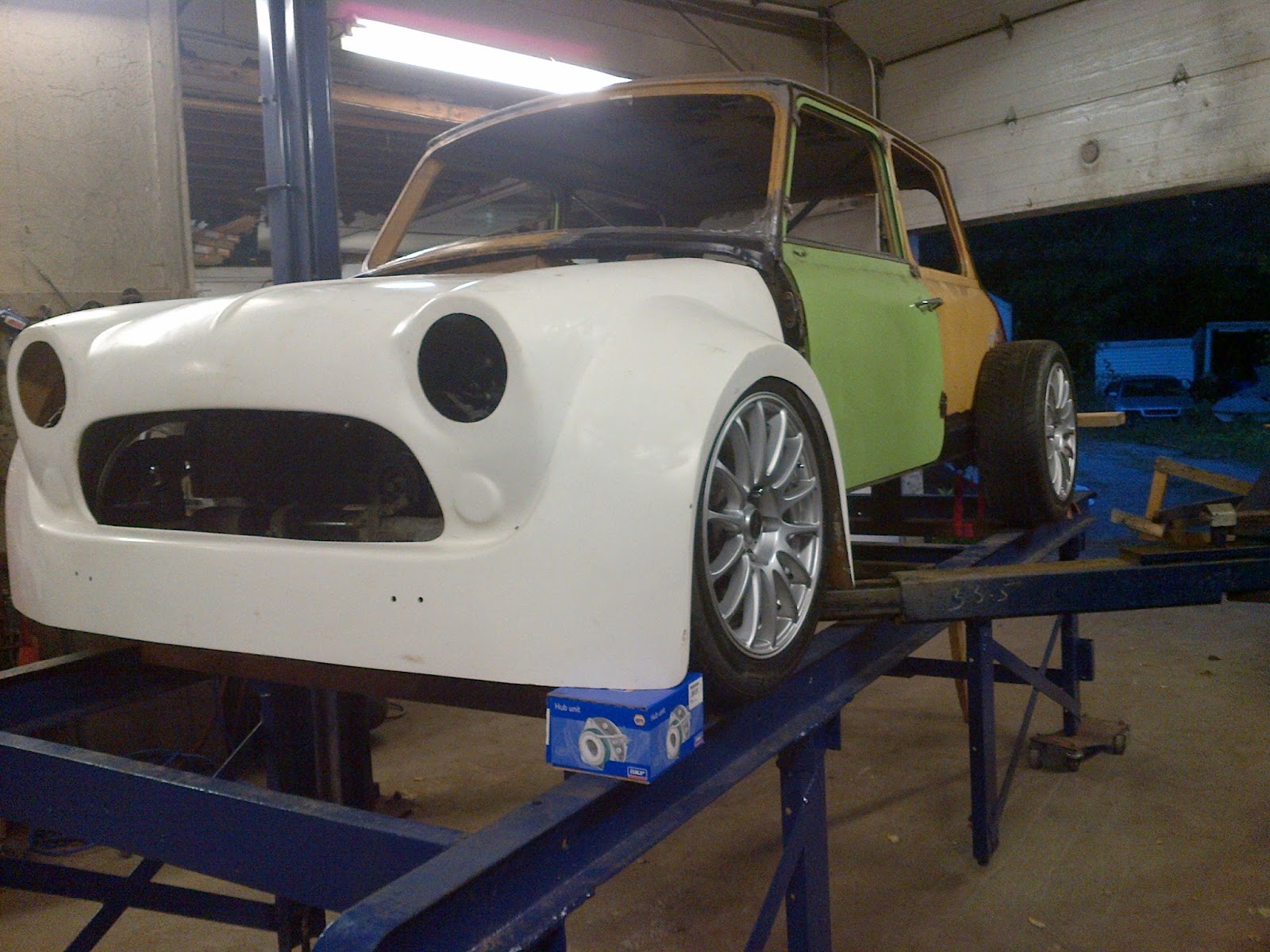
Dropped the fiberglass nose over the front end to get some idea as to how well it fits....it's not sitting at correct height, but it's almost dead on in regards to width, will only require some minor adjustment on the flares to fit perfect !


WARNING: Extremely graphic photo in next section.

I need to take moment to highlight the importance of always using proper safety gear when working with and around shop equipment. In a momentary lapse of better judgment, I proceeded to use an air powered grinder with a minor small chip in the disc. Needless to say when it caught an uneven point on a piece of steel I was cleaning up, it completely and dramatically exploded ....with extremely painful consequences.  Even though I was wearing heavy gloves, it tore through them like butter....that, and my thumb. Luckily no broken bones, and should heal fine, but likely out of commission on the build for few weeks.


Saturday, May 4, 2013

More sheetmetal replacement

Replacing both corners of the lower windshield panel, and rear boot hinge panel along with both lower rear corners. Left side had more rot in it so required making up a larger patch panel.


Filled in the old gas cap hole as well.